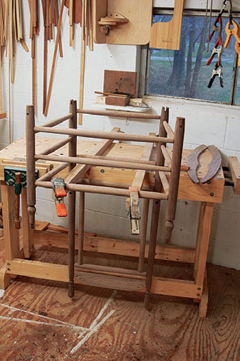
Project: Shaker-Style Woven Rocking Chair
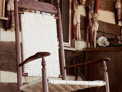
This Shaker-inspired rocking chair combines classic joinery and construction with modern woodworking techniques.
Twenty years ago, I built my first reproduction of a Shaker chair. It was based on a drawing by John Kassay (in The Book of Shaker Furniture) of a fairly yearly New Lebanon rocker. Over the next dozen years or so, I tinkered with the form, giving the arms a more sculpted shape, changing the backrest from slats to a woven panel and introducing new finials and vases. The chair you see here is the current incarnation of that form — one that has remained unchanged for several years because it's exceptionally comfortable and reasonable to build.
For the Shaker Rocking Chair Drawing and Materials List in PDF Format, click here.
I don't use a measured drawing to produce copies of this chair. Instead, this chair (and all others I build) are represented only by sets of story sticks. In the case of this rocker, one stick represents the back posts with back-rung mortise locations marked on one side of the stick and siderung mortise locations on the other. Another stick represents the front posts with side-rung mortise locations on one side and front-rung mortise locations on the other. The post sticks also include graphic representations of vase and finial shapes. I create the chair's bandsawn elements — the arms rockers and crest rail — from traceable scrap-wood patterns. In addition, each of the rungs is represented by a stick cut to the length of the part, with tenon lengths marked on the ends.
Story sticks are common cabinetry and carpentry tools that help reduce the need for measuring everything...and that alone prevents lots of building errors.
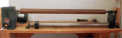
Extra-long Lathe Bed Us a Must
Begin the project by ripping blanks for turning stock on your band saw.
Although I have jigs that help me band saw square turning blanks into octagons, I have abandoned this practice over the years. It's so much easier to simply turn the square blanks round on the lathe.
In order to build full-size post-and-rung rocking chairs, you must have a lathe that can accommodate at least 44" between centers. While it is possible to buy lathes that can be opened up that far, those models are usually quite expensive. My lathe is an inexpensive Craftsman model equipped to handle only 36" between centers. I pulled the lathe-bed tube from the headstock and had a second mounting foot welded to the headstock end of the tube so I can mount the lathe bed anywhere want on the lathe table, giving me, at least in theory, a lathe with an infinite distance between centers. While it might not be possible to modify your lathe in this way, all lathe beds can be lengthened, although some modifications are easier than others.
Turning the Posts and Rungs
Long, thin spindles tend to flex away from the tool as you turn. I'd like to suggest three techniques to counter this tendency. First, choose a midrange lathe speed. I use 1,350 RPM. Too fast, and the spindle will vibrate in a very unsettling manner. Too slow, and the spindle's tendency to flex away from your tool is enhanced. Second, use your off hand as a steady rest. (I sometimes wrap several turns of masking tape around the palm of my right hand — I'm left-handed — and, with that protected palm, I support the back side of the turning directly opposite the lathe tool.) Be sure you keep your fingers dangling down so they can't be drawn up into the gap between the work and the rest. Third, be very careful about the way you move your tool into the work. Don't push it forward. Instead, with the handle well down, lay the heel of the bevel against the rotating work. Then gradually raise the tool's handle until the cutting edge engages the work.
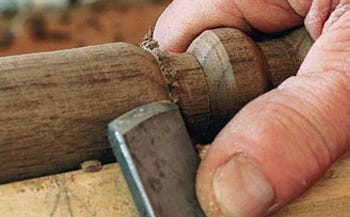
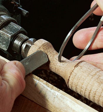
The finials atop the back posts and the vases below the arms are very simple shapes. I begin the finials by forming the flats above and below the full bead with a parting tool. I then roll the full bead with my 1-1/8" skew and use the same tool and technique on the half beads below the bottom flat and above the top flat, as well as the half bead at the very top of the finial.
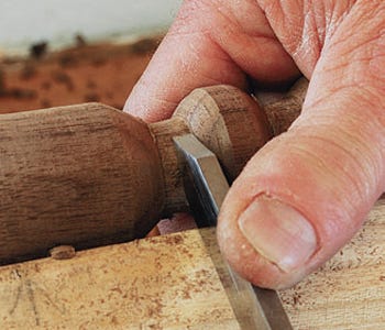
I form the bottom of the front post vase with a 3/8" fingernail gouge working from above and below into the hollow. I cut the taper at the top of the vase with my roughing gouge.
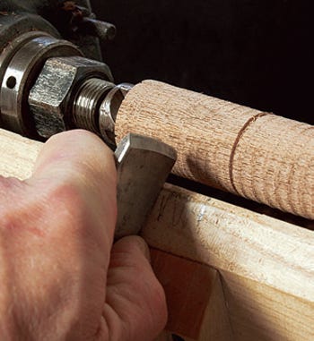
When you're finished shaping the four posts, turn the 14 rungs to shape. Start with blanks at about 4" longer than necessary to allow room for forming the tenons.
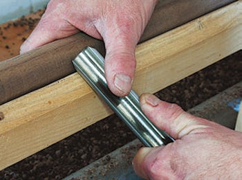
Shaping the Tenons
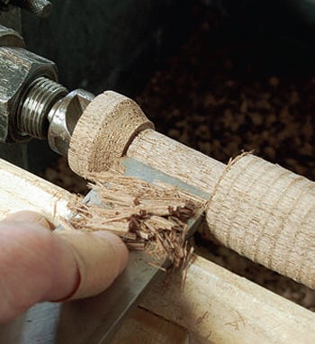
The tenon at the top of the front post and the tenons on the ends of each rung must be carefully formed, because the resulting joints made from fitting these tenons into 5/8" mortises are what principally hold the whole chair together.
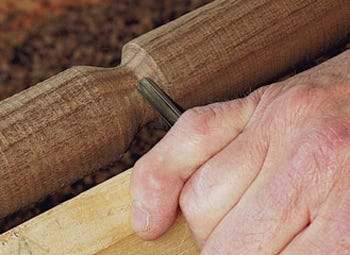
I form the tenons by first working a hollow in the tenon area with a fingernail gouge. When the thinnest diameter of that hollow is 5/8" (measured with a caliper), I lay a very sharp 1" butt chisel bevel-side-down on my tool-rest and carefully feed it into the tenon until its entire 7/8" length is reduced to 5/8".
Tenon fit is critical, and — perhaps oddly — tenons a tiny bit loose are better than tenons a tiny bit snug. Snug tenons can cause major headaches at assembly when you're trying to simultaneously bring a dozen tenons into a dozen mortises.
Once all the parts have been turned, lathe-sand each up to 220-grit. Then remove the parts from the lathe and cut the surplus length off your turning blanks. Because the back posts are relatively thin near the top of the chair, the 5/8"-diameter tenons on the backrest upper rung (the top element in the back panel frame) should be only 9/16" long. Using this same tenon-forming technique, create the 7/16"-diameter x 1/2"-long tenons on the ends of the backrest side posts that will make up the sides of the back panel. Turn all the rung tenons.
Finally, turn the tenons at the tops of the front posts. Make them long enough to accommodate the thickness of the arms, plus some extra that you'll cut flush with the top of the arms.
Locating and Marking Mortises
I use my lathe's indexing head to lay out penciled reference lines to locate the rung mortises.
An indexing head is a disk centered on the lathe's axis of rotation. The disk on my lathe has 36 equally spaced holes drilled near its circumference. A spring-loaded indexing pin allows me to lock the head at any of these 36 stops. I can, therefore, lock the head and draw a line along the length of the outside diameter of the post with my marking jig. That line will be exactly parallel to the lathe's axis of rotation (the post's centerline). In the case of the back posts, after drawing the first line, I release the locking pin, count 10 stops, reset the locking pin and, with my marking jig, draw a second line. These lines are then 100 degrees apart on the post's outside diameter. This 100-degree separation is the angular distance between the centerlines of the back rungs and the centerlines of the side rungs. I repeat the process on the front posts, with one exception: Because the angular distance between the centerlines of the side rungs and the front rungs is only 80 degrees, I count off only eight stops on the indexing head.
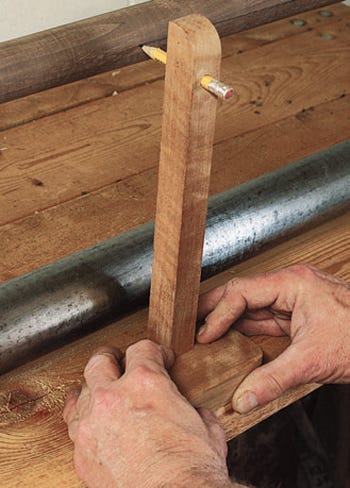
If your lathe lacks an indexing head, here's an alternative method. First, rip a flat carpenter's pencil along its length so the lead is exposed from end to end. Then, on your bench top, clamp a pair of posts together. Lay one ripped half of the carpenter's pencil — exposed lead down — across the pair of posts. Slide the pencil along the lengths of the posts. This will leave behind a line along each post that is parallel to its centerline. Then rotate the posts (approximately 100 degrees for back posts and approximately 80 degrees for front posts), re-clamp them, and create a second line by drawing the ripped pencil along the lengths of the posts.
Estimating 100- and 80-degree increments may sound foreboding, but it's not. Remember that the 100-degree distance is just a bit more than 90 degrees and the 80 a bit less. All you really need at this point is an estimation so you have something on which to mark mortise locations along the lengths of the posts. The exact angular positions will be created later using two types of rung-mortise jigs.
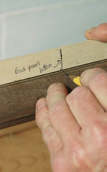
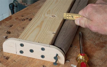
After you've drawn reference lines along all the posts using whichever method for establishing these lines, lay a story stick along one line on one post. Mark the mortise locations along the length of the post by transferring the information from the stick to the post. Be very accurate with these placements along the lengths. Then rotate the post to the other line, flip the story stick over, and transfer the other set of mortise locations. (Editor's Note: You must have one left front post and one right front post. Two matching posts won't work. Same rule applies to the back posts.)
Drilling Rung Mortises with Jigs
To simplify drilling the rung mortises, I devised two very simple rung-mortise jigs: the side-rung mortise jig (SRMJ) and front-rung mortise jig (FRMJ). They'll work for any chair with back rungs 100 degrees from the side rungs, and that includes many, many Shaker chairs. In use, you'll need to support each of these jigs on a large, flat surface on your drill press. Build both the jigs now from scrap.
For the Drilling Jig Diagram in PDF Format, click here.
The purpose of the FRMJ is to keep the posts from rotating as you drill the 5/8" mortise holes. Snug the first post up against the side of the jig so the layout line along the length of the post is parallel to the jig's long leg. Then lock the post into place by turning two screws into the end grain of the post.
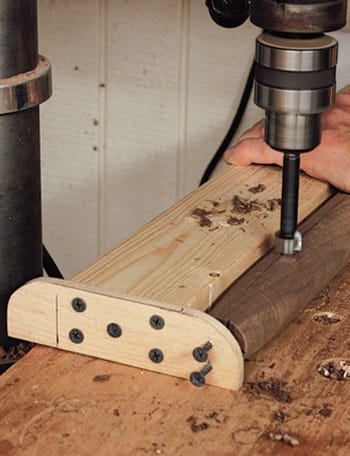
With the post locked, line up the first mortise location under your drill bit. (Be sure to have the drill press set to drill a 15/16"-deep hole in the post. This is best established by drilling into a scrap test piece turned to the correct diameter.) Drill the back-rung mortises in your back posts and your front-rung mortises in your front posts. (Editor's Note: Be sure not to drill any side-rung mortises with the front-rung jig — it's an easy mistake to make and impossible to fix without remaking new leg blanks.)
Before you put the FRMJ away, drill a pair of 1/2"-diameter mortises near each end of the top two backrest rungs (the top and bottom elements of the back panel). These are the mortises that will accept the 7/16"-diameter tenons on the ends of the backrest side posts.
Assembling the Ladders
The front ladder is now ready to be assembled. Do a dry fit, then apply glue to the all the joint parts and tap the ladder together with a soft mallet to start the tenons. Close the joints with a long clamp. Check the ladder with a framing square. Rack it into square if necessary, making sure it lies flat on a flat surface, then set it aside to cure. DO NOT leave a clamp installed on the assembly, which could deform it...the glue will make this error permanent. Just let it dry flat and unclamped.
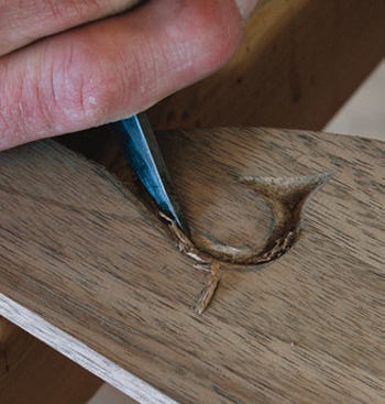
Band saw the crest rail to shape and finish the edges. I carve the ends of my rails, but this is optional.
For the Rocker Elevation and Ladder Drawings in PDF Format, click here.
Chop a crest rail mortise in each of the back posts. The back ladder will then be ready to assemble. A dry fit is particularly important here because the backrest parts and the back ladder should be assembled at once. When everything is just the way you want it, assemble the joints with glue, use a clamp if needed to close them, and let the back ladder dry unclamped on a flat surface.
Drilling the Side-Rung Mortises
When the ladders are fully dry, it's time to drill the side-rung mortises. I'll save you the geometry lesson and just say that you can use the same side-run mortising jig (SRMJ) to drill the side-rung mortises in both ladder assemblies.
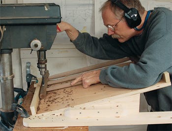
Here the jig is set up to drill side-rung mortises in the front ladder. I simply clamped the jig to my drill press table so that when I brought the bit into the front post, it drilled a mortise along the centerline of that post, exactly 15/16" deep. It may take a bit of experimentation to get this set up correctly, so experiment using a section of scrap turned to the correct diameter. Once everything is dialed in, slide the front ladder along the jig, drilling the three side-rung mortises on that post. Then turn the ladder around and drill the three mortises in the other post.
To drill the side-rung mortises in the back ladder, rotate the jig 180 degrees on the drill press table and clamp it in place to bore mortises along the centerlines of the posts. Again, make these exactly 15/16" deep. Work out the setup on scrap first. (Editor's note: Be sure to drill the mortises for the tenons at the back of each arm now, while the back ladder is on the SRMJ.)
Assemble the Chair Frame
Once all the side-rung mortises are drilled, dry-fit the chair frame together by placing all of the siderung tenons into their mortises. If you've got a good fit, pull the assembly apart, brush glue onto the parts and squeeze the front and back ladders together with a clamp. Allow the glue to dry thoroughly.
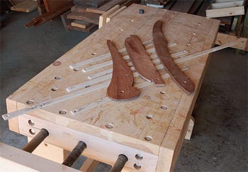
Making the Arms and Rockers
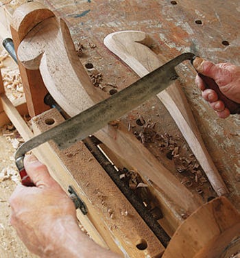
Make patterns for the arms and rockers, and trace them onto your project stock. Saw the rockers and arms to shape. I fair the arms by hand, using a series of pencil marks to set the transition areas for shaping. I rough-in the long-grain bevels with a drawknife. The arms are then finished with chisels, rasps and sandpaper. Now whittle the 7/8"-long, 5/8"-diameter tenons on the ends of the arms, and drill the front post tenon mortises.
For the Rocker Post Back and Arm Drawings in PDF Format, click here.
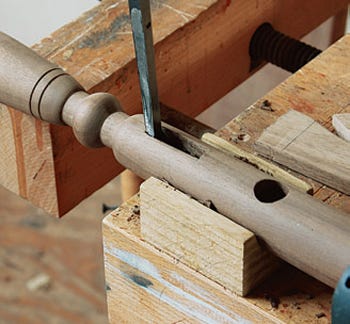
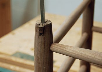
The through tenon at the top of the front post is held in place with a wedge that tapers from about 1/16" at the very top of the front post to nothing at the base of the tenon. I also drill a 1/8" through relief hole at the base of this notch to reduce the likelihood of splitting when the locking wedge is tapped into place. (Editor's note: These wedges must run approximately perpendicular to the grain direction of the arms.) When laying them out, rest a straightedge across the tops of the front posts parallel with the front rungs and draw centerlines for these wedge slots. Using a fine backsaw, carefully slice the wedge slots.
Once the arms have been dry-fit, apply glue to the tenons and into the mortises and work the arms into position. Apply glue to the wedges and tap them home. Trim the tenons and wedges flush.
To cut the rocker notches in the bottoms of the posts, clamp the inverted rocker to your bench. Draw a line connecting the centers of the front and back posts to accurately mark the centers of the rocker notches you'll cut next.
The notches in the front post should be cut 1-3/8" deep on the front and back faces of the post.
The notches for the back posts are a little different. To accommodate the curved rocker, the back post notches are 3/4" deep on the front side of the post and 7/8" deep on the back side. Slice the sides of the notches with a backsaw.
Then, drill a 3/8"-diameter hole — from the front to back — right through the post at the bottom of the notch. Break out the waste very carefully with a sharp mortising chisel, and pare the notches to slowly refine the fit of the rockers. Fix the rockers in their notches with a 1/4"-diameter dowel driven through each post.
Finishing and Weaving
Sand the entire chair up through the grits to 320, and apply the first coat of finish. It's time to weave the seat. Save additional coats of finish until after the seat and back have been woven. This way, you can clean up any scuff marks the weaving process might create, then follow with final finish.
You're done! Ease into that new rocking chair and relish its woven comfort. It's been an ambitious project, but you've just proven your mettle as a budding Shaker chairmaker.


Keep the inspiration coming!
Subscribe to our newsletter for more woodworking tips and tricks