How Dust Collection Systems Work
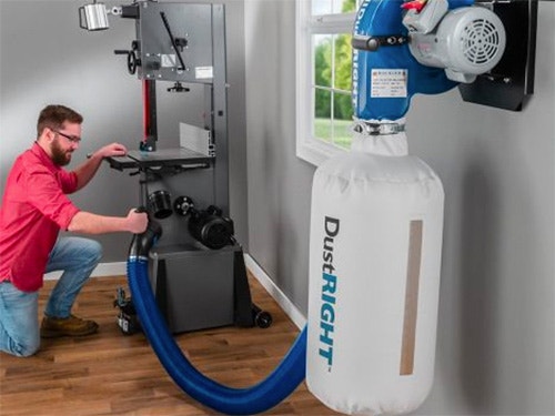
A dust collection system works by capturing woodworking dust and debris in a stream of air and transporting it through the system's ductwork to a collection area.
A dust collector uses a large induction motor to drive a special type of fan called an impeller. The dust collector's 1HP or greater motor and impeller type of fan are necessary in order to generate the large volume of air flow required to move the substantial amounts of dust and debris produced by woodworking equipment.
Ratings and specs for individual dust collectors are listed on the Rockler website in individual product descriptions under the "Specifications" tab.
Air Flow Velocity and Volume
To keep the chips, shavings and dust moving through the system's ductwork, a dust collector has to keep the air stream in the system moving at a certain velocity, measured in feet per minute (fpm). To keep the volume of debris generated by stationary woodworking tools aloft on its way to the collector, the system also has to move a certain (fairly large) volume of air, measured in cubic feet per minute (cfm).
Air Velocity (fpm) and Dust Collection
Experts generally agree that the air speed needed to keep woodworking debris moving through a dust collection system's ductwork is 3500 fpm for main ducts, and 4000 fpm for branch ducts that serve individual tools.
Wood dust becomes a potential health problem when wood particles from processes such as sanding and cutting become airborne. Breathing these particles may cause allergic respiratory symptoms, mucosal and nonallergic respiratory symptoms, and cancer...
Air Volume (cfm) and Dust Collection
Estimates of the air flow volume levels necessary to adequately handle woodworking chips and dust, on the other hand, vary some from source to source, depending in part on what is meant by the term "dust collection." Higher estimates for a given power tool are likely to represent the air volume necessary to capture nearly all of the dust output from a woodworking tool (including the fine, airborne dust) and can be much higher than the volume necessary for the less ambitious goal of capturing the majority of the bulky chips, large particle dust, and shavings that would otherwise clutter-up your shop floor.
Air volume requirements also vary depending on the debris output of the tool. In general, the range for effective chip, shaving and large particle dust control is between 300 cfm for a tool with a lower dust and debris output, such as a scroll saw, and 900 cfm for a tool that really puts out the shavings, like a 24' thickness planer.
Many power tool manufacturers publish minimum cfm requirements for each of their power tools. We encourage you to consult with the manufacturer of the tools in your shop before selecting and designing your dust collection solution. To give you a rough ideal of what you'll need in terms of air flow volume, the chart below lists common cfm requirements for popular shop machinery.
| Machine | CFM Requirements |
| Table Saw - 10" | 350 - 450 |
| Band Saw - 14" | 350 - 400 |
| Jointer - up to 8" wide | 350 - 450 |
| Planer - 12" | 500 |
| Planer -15" and larger | 600 - 900 |
| Disc Sander - 12" | 300 - 350 |
| Horizontal Belt Edge Sander | 550 - 600 |
| Vertical Belt Sander - up to 6" wide | 400 - 450 |
| Drum Thicknessing Sander - up to 12" drum | 400 |
| Drum Thicknessing Sander - 12" - 24" drum | 550 |
| Drill Press | 300 |
| Scroll Saw | 300 - 350 |
The Relationship between Air Velocity and Air Volume
Simply stated, the relationship between air volume (cfm) and air velocity (fpm) in an air handling system is a function of the size of duct that the air stream is moving through: A stream of air moving at a speed of 4000 fpm through a 12" diameter round duct is transporting a greater volume of air than a 4000 fpm air stream moving through a 3" diameter duct. As a matter of fact, the difference is significant. The 4000 fpm air stream in the 12" diameter duct is moving 3142 cubic feet per minute (cfm) of air volume, whereas the 4000 fpm air stream in the 3" diameter duct is moving only 62.5 cfm.
In choosing a dust collector and designing a dust collection system, it is important to remember that air volume and velocity are interrelated. As you might expect, it takes a more powerful dust collector to move a large volume of air at a speed sufficient for effective dust collection than it does to move a small volume of air. Your dust collection system must be capable of delivering the minimum required cfm to each machine, and it must be able to do so while moving the air at the minimum recommended velocity.
Static Pressure
Friction is the dust collection system's enemy. As an air stream moves through an air handling system, it rubs up against the surfaces of ductwork, has to round corners, is forced through restrictions, etc. - all of which inhibit air flow and create power demands on the system. Static pressure (SP), measured in inches of water in a column, is the resultant loss in speed and volume of the air stream.
Static pressure build-up in a dust collection system is influenced by a number of factors. An excessive number of turns in the air stream produced by elbows, wyes, and T's are primary culprits in building up static pressure losses that hamper the system's performance. Duct size also plays a major role. The static pressure losses in in straight runs of narrow diameter ductwork are far more severe than in comparable runs of a larger diameter duct.
Dust collectors are usually rated to stand up to a certain maximum amount of static pressure. If a dust collector is rated for a maximum static pressure of 12 inches of water (near the top of the range for dust collectors) it will cease to move air at all when the demands of a system's ductwork reaches 12 inches of static pressure. In setting up a dust collection system, one of the main challenges is to design a system that will move air with enough force to overcome static pressure losses and still deliver the air velocity and volume necessary to effectively transport woodworking debris.


Keep the inspiration coming!
Subscribe to our newsletter for more woodworking tips and tricks